Long Distance CO2 Transport
CO2 capture and storage or CO2 sequestration (often known by its acronym CCS) - is the term used to describe a set of technologies aimed at capturing carbon dioxide emitted from industrial and energy-related sources before it enters the atmosphere, compressing it, and injecting it deep underground in secure geological formations, and ensuring it remains stored there indefinitely
For the next discussion the user should consider the critical properties of CO2:
Tc = 31 °C, Pc=74 bar.
So any cross of temperatures below 31°C and pressures lower than the critical
pressure is accompanied by a phase change
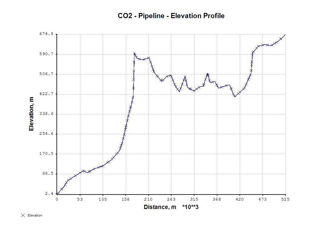
This sample shows the transport of pure carbon dioxide generated by some electric-power-plant located on the sea coast through a long distance pipeline about 500 km long to some oil reservoir located at a higher elevation above sea level. At the delivery point CO2 will be either stored or used for enhanced oil recovery.
The profile of the transfer line is shown on the next figure.

The transported fluid is considered pure CO2 and the very small impurities are excluded from the simulation The fluid is received at 55°C and at 250 bar. The initial flowrate considered is 600000 kg/h. A number of calculations with different internal diameters and flowrate are performed in order to find a viable combination. A suitable internal diameter equal 0.463 m represent a possible solution for the specified fluid flowrate.
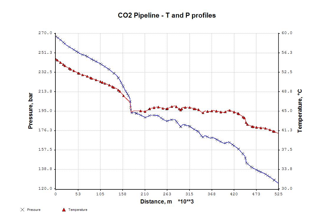
The profile of pressure and temperature along the pipeline is shown on the next figure.

The fluid is delivered at a pressure slightly over 120 bar and at a temperature of about 41°C. The CO2 fluid is transported in the dense gas phase region; the temperature is always over the critical temperature. Similarly the pressure is always higher than the critical pressure.
From a point of view interested in model testing the above simulation is not much interesting. A more interesting simulation is when the pure co2 enters the two-phase region and some segments of the pipeline will operate in two phase flow exibiting liquid hold-up and thermal effects associated to condensation/evaporation.
For the thermodynamic simulation of CO2 transport some simulators use the Span-Wagner equation of state. This equation has some disadvatages since it can strictly applied only to pure CO2. Using XPSIM the GERG-2004 model can be used; it provides thermodynamic values for pure CO2 with the same precision of the SPan&Wagner model, in addition it can be used to simulate fluids not composed of pure CO2: light hydrocarbons, water, nitrogen and other gases are treated by the GERG-2004 equation of state.
Pure fluid transport in dense phase is not a difficult task. A more interesting simulation is the event of the formation of coexisting vapor and liquid phases along the pipeline.
In this case the formation of an equilibrium phase entrains the evaluation of of the liquid holdup and isenthalpic flash evaluations
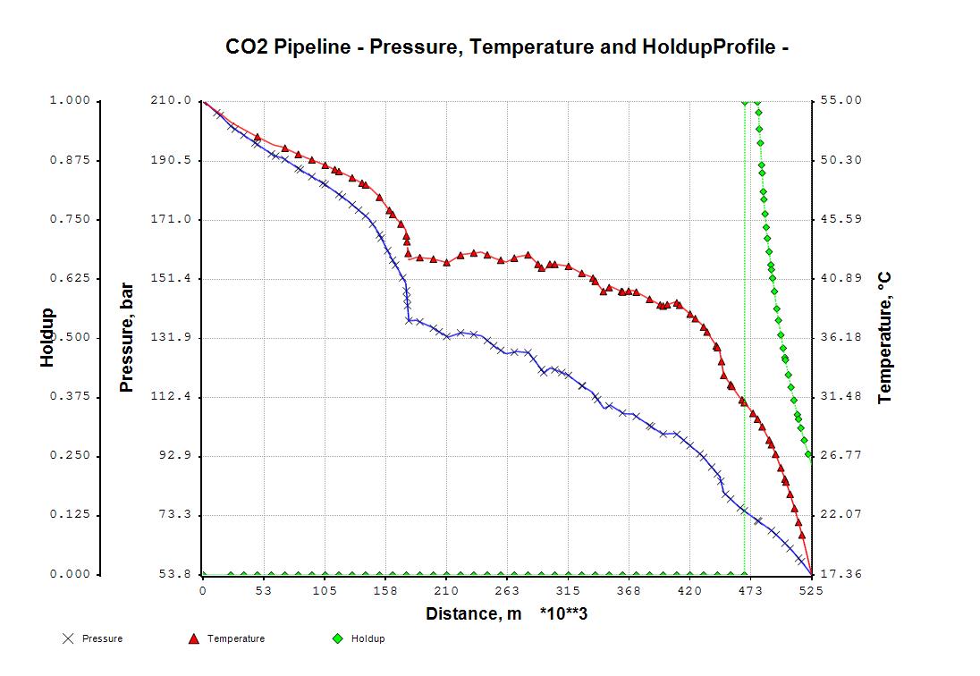
So at about 473 km the fluid crosses the critical temperature and soon after enters in the two-phase coexistence region. As shown in the next figure the liquid hold-up sharply encreases to 1.0 and then diminishes with the pressure lowering reaching a value of 0.25 at pipeline exit.

Simulation Input
<*
*
RUN ID='CO2 TRANSP' CUSTOMER=STAFF PROJECT='CO2 TRANSPORTATION'
*
DESC CO2 TRANSPORTATION
*
DIMENSION INPUT SI PRES=BAR
*
*
System Data
*
*
*
CHEMCOMP CO2
*
THERMSET UID=M1
METHODS K=SRK HS=LK CP=LK D=LK IV=LK TRAN=ELYHAN SURT=IDEAL
*
THERMSET UID=GERG
METHODS K=SRK HS=GERG04 CP=GERG04 D=GERG04 IV=LK TRAN=ELYHAN +
SURT=IDEAL
*
THERMSET UID=SRK
METHODS K=SRK HS=SRK CP=SRK D=SRK-P IV=SRK TRAN=ELYHAN SURT=IDEAL
*
*
Default Data
*
*
*
MATERIAL UID=STEEL CP(KJ/KG-C)=0.447 DENS(KG/M3)=7850 K(W/MC)=45
*
MATERIAL UID=SAND CP(KJ/KG-C)=0.84 DENS(KG/M3)=1600 K(W/MC)=0.7
*
WALL UID=ESPOSTO
LAYERS MAT=STEEL THICK(MM)=22.2
*
WALL UID=INTERRAT
LAYERS MAT=STEEL THICK(MM)=22.2 / MAT=SAND THICK=3100
*
AMBIENT UID=WINTER AIR TEMP=-2.5 V(MT/SEC)=2.5
*
AMBIENT UID=SUMMER AIR TEMP(CENT)=48.2 V(MT/SEC)=2.5
*
*
Flowsheet Data
*
*
*
SETMETH UID=SRK
*
STREAM=S1 TEMP=55 PRES=250 RATE(W)=600000 XBASIS=M
COMP CO2:100
*
PIPELINE IN S1 OUT S2 UID=PL1
PARA PHASE=MIX COORD=PROJ LUNIT=KM STEP(MT)=500
CORRELAT SET=MECH2F
POINT DIST(MT)=0 ELEV(MT)=5.43 DIAM(MT)=0.463 ROUGH(MICR)=45 +
AMB=SUMMER WALL=INTERRAT
POINT DIST=1677.1 ELEV=2.44
POINT DIST=8691.9 ELEV=20.105
POINT DIST=15300.4 ELEV=32.379
POINT DIST=24048.6 ELEV=58.64
POINT DIST=38269.8 ELEV=75.22
POINT DIST=60564.3 ELEV=100.171
POINT DIST=69030.4 ELEV=91.8165
POINT DIST=83812 ELEV=107.189
POINT DIST=105594 ELEV=121.026
POINT DIST=124643 ELEV=146.238
POINT DIST=143266 ELEV=184.375
POINT DIST=151198 ELEV=228.061
POINT DIST=162536 ELEV=323.147
POINT DIST=168745 ELEV=365.827
POINT DIST=174927 ELEV=413.108
POINT DIST=177468 ELEV=595.068
POINT DIST=184030 ELEV=572.985
POINT DIST=197218 ELEV=567.601
POINT DIST=211213 ELEV=576.367
POINT DIST=223096 ELEV=514.435
POINT DIST=240274 ELEV=477.049
POINT DIST=251920 ELEV=497.216
POINT DIST=261653 ELEV=502.721
POINT DIST=270938 ELEV=459.768
POINT DIST=281054 ELEV=432.209
POINT DIST=294218 ELEV=496.952
POINT DIST=299581 ELEV=450.967
POINT DIST=314896 ELEV=436.251
POINT DIST=327010 ELEV=452.753
POINT DIST=336051 ELEV=456.54
POINT DIST=345963 ELEV=511.964
POINT DIST=351608 ELEV=471.28
POINT DIST=362837 ELEV=476.431
POINT DIST=370960 ELEV=448.096
POINT DIST=387062 ELEV=458.132
POINT DIST=396670 ELEV=462.046
POINT DIST=407905 ELEV=411.159
POINT DIST=430544 ELEV=447.741
POINT DIST=445997 ELEV=509.613
POINT DIST=449445 ELEV=597.005
POINT DIST=462257 ELEV=624.635
POINT DIST=477657 ELEV=631.628
POINT DIST=492279 ELEV=627.226
POINT DIST=507073 ELEV=644.337
POINT DIST=518502 ELEV=661.843
POINT DIST=525327 ELEV=674.785
CALC ALG=2
PRINT PROP
*
END